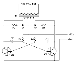
dc ac inverter circuit diagram using 555 timer

The file or resource you have requested cannot be found on this server. Through a series of highly sophisticated and complex algorithms, this system has determined that the file you requested could not be found on this server. It could be that you simply mistyped a URL, or it could be that you are some sort of interplanetary alien-being that has no hands and thus cannot type. If I were a gambler, I would bet that a cat (an orange tabby named Fluffy or Miss Kitty Fantastico) somehow jumped onto your keyboard and forgot some of the more important pointers from those typing lessons you paid for. Based on the actual error encountered, I would guess that the feline in question simply forgot to place one or both paws on the appropriate home keys before starting. Then again, I suppose it could have been a keyboard error caused by some form of cosmic radiation; this would fit nicely with my interplanetary alien-being theory. If you think this might be the cause, perhaps you could create some sort of underground bunker to help shield yourself from it.
I don't know that it will work, but you will probably feel better if you try something. Another suggestion is to try a tinfoil hat, though they generally provide protection only to the cranial region and ignore other vital body parts. Back to Homepage | Clap Switch is a basic Electronics mini-project, made with the help of the basic components. Clap Switch has the ability to turn ON/OFF any electrical component or circuit by the clap sound. It is known as Clap Switch, because the condenser mic which will be used in this Project will have an ability to take the sound having same pitch as the Clap sound as the input. Although it doesn’t mean that the sound will have to be of Clap sound, it can be any sound having the same high pitch as of Clap. We can also say that it converts the Sound energy into the Electrical Energy, because we are giving an input to the circuit as a sound whereas the Circuit gives us the output as a LED glow (Electrical Energy). As already mentioned, this project is basic Electronics mini-project, so this project is made of the basic components.
Following is the list of the components required to make the Clap Switch. This circuit (As shown below) is made with the help of Sound activated sensor, which senses the sound of Clap as input and processes it to the circuit in order to give the Output. When sound is given as the input to the Electric Condenser Mic, it is changed into the Electrical Energy as the LED turns on. LED turns ON, as we give sound input and it turns OFF automatically after few seconds. Turn-On LED timer can be changed by varying the value of 100mF capacitor as it is connected with 555 timer whose main purpose is to generate the pulse. Although the name of the circuit is the Clap Switch, but you are not restricted to give input as the Clap only. It can be any sound, having same pitch as of Clap so this can also be called as “Sound Operated Switch”. This circuit is mainly based on transistors, because the negative terminal of Mic is directly connected with the transistor. In this circuit, we haven’t used any Electronic Switch to turn on/off the circuit, so when you are connecting the battery with the circuit, it means your circuit is now turned ON and it will take the inputs in the form of Sound Energy.

You can modify this circuit by using Relay as Electronic Switch to turn the circuit ON or OFF. As soon as we give the sound input to the circuit, it amplifies the sound signals and proceeds them to the 555 timers which generates the pulse to the LED, making it turn ON. You are to make sure, that the negative side of the Condenser mic is connected with the amplifier or the circuit will heat-up and may not working with different models of transistors etc.
stand alone ac unit walmartYou cannot increase the sensitivity of the Condenser mic for long usage, it has short range by default.
rooftop packaged air conditioning units ukIt is also applicable for the LAMP, so this circuit has many opportunities for modification.
integrity auto repair tampa fl
Clap Switch is not restricted to turn the LEDs ON and OFF, but it can be used in any electric appliances such as Tube Light, Fan, Radio or any other basic circuit which you want to turn ON by a Sound. You may also check these simple and easy DIY EE Projects : Electrical and Electronics Projects EasyEDA: A Powerful Free Circuit, Simulation & PCB Design Tool555 Timer IC: Introduction, Basics & Working with Different Operating Modes 555 Timer IC: Introduction, Basics & Working with Different Operating Modes Basics of 555 Timer IC Working with 555 Timer IC Monostable & Bistable MultivibratorLessons In Electric Circuits, Volume 3, chapter 8: “Positive Feedback” Lessons In Electric Circuits, Volume 4, chapter 3: “Logic Signal Voltage Levels” Schmitt Triggers have a convention to show a gate that is also a Schmitt Trigger, shown below. The same schematic redrawn to reflect this convention looks something like this: The 555 timer is probably one of the more versatile “black box” chips.
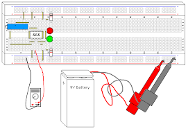
Its 3 resistor voltage divider, 2 comparators, and built in set reset flip flop are wired to form a Schmitt Trigger in this design. It’s interesting to note that the configuration isn’t even close to the op amp configuration shown elsewhere, but the end result is identical. Try adjusting the potentiometer until the lights flip states, then measure the voltage. Compare this voltage to the power supply voltage. Adjust the potentiometer the other way until the LED’s flip states again, and measure the voltage. How close to the 1/3 and 2/3 marks did you get? Try substituting the 9V battery with a 6 volt battery, or two 6 volt batteries, and see how close the thresholds are to the 1/3 and 2/3 marks. Schmitt Triggers are a fundamental circuit with several uses. One is signal processing, they can pull digital data out of some extremely noisy environments. Other big uses will be shown in following projects, such as an extremely simple RC oscillator. The defining characteristic of any Schmitt Trigger is its hysteresis.