how do hvac induction units work

Updating Buildings with Old Induction Systems… Induction HVAC systems were very popular in the 1950s and 1960s. They were used in large buildings where space was at a premium and the small ductwork used with the induction systems was an advantage. The induction units were typically mounted on the floor or the wall in the building’s perimeter zones, and concealed under enclosures built to suit the size of the units selected. With the emergence of variable air volume systems in response to the energy crisis in the 1970s, induction system fell into disfavor. There were energy cost concerns as the old induction units required very high inlet static pressure (often 1.5 – 3.0 in. w.c. or more) which imposed a significant penalty of the systems fan energy consumption. In addition, the old induction units produced relatively high noise levels. Many of these older building are now in need of updating. Rather than simply replacing the old induction units with like units, there is often an opportunity to significantly improve the performance of the old induction HVAC system through the use of new induction units which incorporate the latest induction nozzle technology, while re-using much of the buildings existing infrastructure (ductwork, piping, etc).

Very low noise levels can be achieved when the new induction units are sized at relatively low inlet static pressures. With the new units selected at typical inlet static pressures of 0.5″ w.c. or less, room noise levels can be dramatically reduced as the new technology nozzles are whisper quiet. DADANCO’s patented nozzles rapidly induce room air to reduce the momentum and height the primary air jet, which significantly reduces the noise generated. In many buildings the cooling loads have increased from what was anticipated when the building was originally designed and built. This is often due to the use of more heat-producing electronic equipment within the building such as computers and equipment in offices, medical equipment in hospitals, etc. The old induction units were not sized for these increased cooling loads and often cannot now adequately cool the rooms. If increasing induction unit cooling capacities within the same unit space constraints is an objective the new induction units can be selected at inlet static pressures and primary airflows close to the original conditions, while providing more cooling capacity through the new induction unit’s water coil.

As there is normally excess water chiller cooling capacity available in most buildings, the room temperatures can now be maintained at acceptable levels.
auto body repair shops tempe az Many building owners want to remove the unsightly old induction units and enclosures from the floor.
fujitsu wall air conditioning unitsDepending on the heat losses along the buildings perimeter it is often possible to replace the old floor-mounted units with new concealed ceiling-mounted models.
rooftop ac unit troubleshooting The net result is a gain in floor space and overall improvement to the room’s appearance. With the new nozzle technology available today the induction systems supply fan static pressure can be dramatically reduced (often by 1.0 – 3.0″ w.c.) when retrofitting an entire system with new induction units.
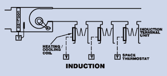
In addition the primary airflow can often times also be reduced (within the constraints of the ventilation air requirement). The net result of these decreases in static pressures and primary airflows due to the use of the new induction units is lower fan energy consumption and operating costs. What is an induction unit? Primary supply air from the central system air handling units is introduced into the induction unit through a series of nozzles (2). This induces room air (3) into the induction unit and in turn through a secondary water coil (4). Induced room air is cooled and/or heated by the water coil to the extent needed to control the room temperature. Induced room air is then mixed with the primary supply air and the mixed air (5) is discharged into the room. Induction Units Product Range DADANCO’s Induction units have been developed using our patented nozzle technology. We offer several designs that can fit into the existing enclosures of most brands and models sold in the past and which may be in need of replacement or updating.

Our standard units are the FMTBY (approximately 20” high x 7” deep), the FMLBY (approximately 12” high x 9” deep), and the FMFBY (approximately 11 ½” high x 11” deep). All models are available with unit lengths from 24 inches through 96 inches and with either a 2-pipe or 4-pipe configuration. Water Control Induction Air Terminals 20 to 130 Cfm Induction air terminals offer: Positive ventilation with constant air movement Automatic actual load adjustment Heating and cooling operation with 2-pipe of 4-pipe system options Published on May 22, 2011 AIR CONDITIONING FOR LARGE MULTISTORY BUILDINGS
PREPARED BY
NOOR AZILA BINTI JAMARI
LECTURER
CIVIL ENGINEERING DEPARTMENT
Most large multistory buildings use highly centralized air conditioning equipment. The roof and basement are the usual choice for these central station systems.
The basement has the advantage of easy utility connections, noise isolation, not being valuable rental area and the fact that structural loads are not a problem.
INTRODUCTION

The roof is the ideal location for fresh air intakes and heat rejection to the atmosphere.
Cooling tower are noisy, produce very hot and humid exhaust air, so the best location for cooling rower is placed on the roof.
SECTION OF A TYPICAL MULTISTORY BUILDING WITH A ROOFTOP CENTRAL STATION MECHANICAL SYSTEM
In most buildings, the mechanical equipment is shown to be on the roof. This section shows an all-air system served by a single central air handling unit on the roof.
To avoid the large vertical ducts, separate air handling units can be placed on each floor and only water circulates vertically. This saves much energy because moving air great distances requires much power.
MECHANICAL EQUIPMENT IS STILL ON THE ROOF, EACH FLOOR HAS A SEPARATE AHU
The advantage of all-air system is complete control over air quality is possible. The disadvantage is that all-air systems are very bulky and a significant part of the building volume must be devoted to them.

There are 5 system in all-air system categories.
i. Central Plants
ii. Variable Air Volume (V.A.V)
iii. Terminal Reheat System
iv. Multizone System
v. Double Duct System
ALL-AIR SYSTEM
The central air conditioning system has the limitation of the same air quality being delivered throughout the building.
If the structure is zoned or divided and compartmented into several different functions such as offices, workshops, canteen.
The temperature of each element can be controlled with zoned thermostats.
The fan precedes the chiller and reheater coils and blow air through the air-handling unit.
Several ducts radiate from the unit to designated zones within the building.
CENTRAL PLANTS SYSTEM
CENTRAL PLANTS SYSTEM
This is a single duct system that can easily have many zones. A variable air volume control box is located wherever a duct enters a separate zone.
A thermostat in each zone controls the air flow by operating a damper in the V.A.V control box.

More cooling is required, more cool air is allowed to enter the zone. VARIABLE AIR VOLUME SYSTEMS
VAV system.
Floor plan of a VAV system.
VAV control box.
At the first the terminal reheat system looks just like the V.A.V system but in fact it is very different.
This system has terminal reheat boxes in which electric strip heaters or hot water coils reheat air previously cooled.
All others zones will reheat the cold air to the desired temperature.
iii. TERMINAL REHEAT SYSTEM
Terminal reheat system.
In this system, every zone receives air at the required temperature through a separate duct.
These ducts are supplied by a special multizone air handling unit that custom mixes hot and cold air for each zone.
This is accomplished by motorized dampers located in the air handling unit but controlled by thermostats in each zone. Depending on the temperature, the ratio of hot and cold air varies but the total amount of air is constant.

The multizone unit is supplied with hot water, chilled water and a small amount of fresh air.
Each multizone unit can handle about 8 zones.
Because moderate air temperatures are created by mixing hot and cold air, this system also wasteful of energy.
Disadvantage this system are costs relatively high while the thermal control is relatively poor.
Like the multizone system, the double duct system mixes hot and cold air to achieve the required air temperature.
Instead of mixing the air at a central air handling unit, mixing boxes are dispersed throughout the building.
The double duct system creates a high level of thermal comfort and allows for great zoning flexibility, it is very expensive, requires much building space and its wasteful of energy.
v. DOUBLE DUCT SYSTEM
Double duct system.
To reduce the size of the ducts, a high-velocity version of this system
High-velocity air systems (6000 feet/minute) consume more fan power than normal velocity systems(2000 feet/minute).
Because of these problem and because V.A.V system are a good alternative, dual duct systems are not used much anymore.

These system supply both airand water to each zone of a building.
It greatly decreases the size of the equipment because of the immense heart-carrying capacity of water as opposed to air.
Air is supplied mainly because of the need for ventilation.
There are 2 system in air-water system categories.
i. Induction System
ii. Fan- coil with supplementary air
But in this topic is cover induction system only
AIR-WATER SYSTEM
A small quantity of high-velocity air is supplied to each zone to supply the required fresh air and to induce room air to circulate.
Most induction terminal units are found under windows where they can effectively neutralize the heat gain.
As the high-velocity air shoots into the room it induces a large amount of room air to circulates.
This combination of room air and fresh air, then passes over heating or cooling coils.
INDUCTION SYSTEM
Local thermostats regulate the temperature by controlling the flow of either hot or cold water through the coils.
It takes a lot of fan power to circulate air at high velocity throughout a building.
Because of the high cost of energy and the expense of high-velocity ductwork, the use of induction systems is limited.
Induction system.

Induction unit with cooling or heating coils
These systems supply no air.
There are 2 system in all-water system categories.
i. Fan-coil System
ii. Water Loop Heat Pump System
But in this topic is cover Fan-coil system only.
ALL-WATER SYSTEM
The fan-coil unit basically consists of a fan and a coil within water circulates.
The units are in the form of cabinets for placement under windows.
The fan blows room air across coils containing either hot or cold water.
Thermostatically controlled valves regulate the flow of water through the coils.
A 4 pipe system, which is has 2 pipes for hot water supply and return and another 2 pipes for cold water supply and return.
FAN-COIL SYSTEM
Condensation on the cooling coils must be collected in a pan and drained away.
When the fan-coil unit is on an outside wall, it is possible to have an outdoor air intake connected to the unit.
A three-speed fan switch allows occupants of the zone to have some control over the temperature.
Fan-coil units are most appropriate for air conditioning buildings with small zones (eg.