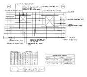
air handling unit autocad drawing

Connect with peers and Autodesk in our forums, read community articles, and submit your ideas.The Visual AHU software is a Windows based sales & production system specially designed for air handling unit manufacturers. Our unique 3D visualisation software allows for the creation and rapid selection of user created components through customisable databases. There are several versions of the Visual AHU software available including: Standard Visual AHU product - The software is installed onto user's PC/Laptop Visual AHU Online - Fully customised web based selection program Visual AHU Lite - Similar to the standard installation but with limited customisation available See below for further details on our Visual AHU software products. If further customisation of the product is required please contact CCSI. Brochure is available for download here Our standard Visual AHU software utilises customisable databases to quickly select and create standard units.

Several upgrades exist including upgrade to our Visual AHU Manufacturing software , Autodesk Inventor integration, Autodesk Revit integration and obtaining EUROVENT certification. View Product for more details. Our Visual AHU Manufacturing software turns your sales into production as a full Bill Of Materials is created and detailed through AutoCAD drawings with a possible link to CNC and MRP software. Please contact us for further information. This version of the Visual AHU software is fully web based and requires an internet connection to be functional.
air conditioning unit for vauxhall corsaThe login page can be fully customised to suit the client's needs.
bypass thermostat window ac unit Similar to the Standard Visual AHU software but with limited customisation available.
car ac repair meridian ms
Home > Design & Construction Standards > Detail Drawings Design & Construction Standard Detail Drawings All Standard Detail Drawings presented herein are intended to assist architects, engineers, other design professionals, contractors and UT staff in understanding the preferences of The University of Texas at Austin in the development, maintenance, construction and repair of its facilities. These Detail Drawings are intended to be used as guidelines. Detail Drawing documents require modification to meet the conditions and appurtenances of each project; therefore the legal responsibility for project document preparation shall continue to reside with the Design Professional. Refer to the Welcome Page for additional requirements. The Detail Drawings were created in AutoCAD 2007 file format; AutoCAD is a registered trademark of Autodesk Inc. Please Note: These Detail Drawing documents are for use by The University of Texas at Austin, its consultants and contractors and remain the property of The University of Texas at Austin at all times.

FLOOR DRAIN INSTALLATION DETAIL MODULAR COMPRESSION PIPE SEAL AND SLEEVE DETAIL WATER, WASTE & VENT PIPING HANGERS & SUPPORTS DETAIL LAVATORY & SINK CONNECTION DETAIL DETAIL: LAB SINK CONNECTION Division 23: Heating, Ventilating and Air Conditioning TYPICAL BRANCH DUCT WITH 45° CLINCH TAP DETAIL TYPICAL BRANCH DUCT WITH CONICAL TAP DETAIL CEILING FIRE DAMPER DETAIL FIRE DAMPER INSTALLATION DETAIL LATERAL MIXING TEE DETAIL VAV FUME HOOD DETAIL (BUILDINGS WITH PNEUMATIC CONTROLS) WATER PIPING HANGERS AND SUPPORTS DETAIL PIPE THRU ROOF DETAIL STEAM HEATING COIL PIPING DIAGRAM REHEAT POSITION STEAM HEATING COIL PIPING DIAGRAM PREHEAT POSITION PIPING SCHEMATIC: STEAM COIL SERIES CHILLED WATER COIL PIPING DIAGRAM CHILLED WATER INSULATION DETAIL AT AHU COIL SCHEMATIC AIR BLEED/TEST VALVE SCHEMATIC PIPING DIAGRAM: STEAM TRAP AT END OF MAIN INSTRUMENT TAPS IN PIPING DETAIL SPLIT CHILLED WATER COIL PIPING DIAGRAM

INSTRUMENTATION & MISCELLANEOUS PIPING TAPS (FOR WATER BELOW AMBIENT TEMP) COOLING COIL MOUNTING DETAILS STEAM CONDENSATE TANK & DUPLEX PUMP DETAIL END SUCTION PUMP PIPING DETAIL AHU - FRONT ACCESS FILTER HOUSING DETAIL MIXING LATERAL CONTROL DIAGRAM LOW TEMPERATURE SAFETY MOUNTING DETAIL THERMOSTAT & DAMPER CONTROLLER ASSEMBLY DETAILWorking efficiently and safely Whether it is in the area of sanitation, heating, and air-conditioning or a large system builder, you are an expert in building services and power engineering and contribute considerably to the energy efficiency of your building and the well-being of its tenants. In this very versatile area of activities, clever concepts that are easy and safe to install and operate are what count. TROX offers system solutions from a single source for new construction and refurbishment, for every building type and every building size. Chilled beam selection program BIM / Revit library BIM and Revit Files

TROX USA BIM/Revit Catalog The TROX USA Revit library is evolving with fully integrated BIM objects. TROX BIM objects now contain performance and selection information allowing engineers to make selections and estimate energy usage of a building.Drawings » Drawings for Make-Up AirDrawings for Make-Up Air What do the icons mean? View In CAPS: Drawing content is now available directly from Greenheck's computer aided product selection program, CAPS. The program is configuration based and creates 2D and 3D models. Equipment schedule information and wiring schematics are shown when available. Transmit: Drawing content is available, however requires the transmission of a CAPS job file (.gfcj) to the Factory. Download: Basic models are available for immediate download. Configured Model Selection CAPS required to Create 3-Axis Machining and Beyond with Fusion 360 Fusion 360CAM 360Fusion 360 Learn how to program parts with prismatic and sculpted/organic-shaped features using 3D machining strategiesLearn tips and tricks to get the most out of an integrated design-to-manufacturing workflow based in Fusion 360Learn how to incorporate workholding into the CNC programming processDiscover how to utilize the CAM capabilities offered in the Fusion 360