trane ac unit wiring diagrams

Search for Current Literature Please Note: For literature of older products, please contact your local Trane sales office. Narrow your search by selecting one or more options below. Trane rooftop units and systems are unitary systems manufactured in various configurations providing single or multi-zone heating,From our 17.5 SEER Precedent™ to our IntelliPak™ with CDQ (Cool, Dry, Quiet dehumidification system), Trane rooftop units technology represent the industry standard in meeting commercial building comfort needs. All of our commercial rooftop units and systems, from 1½ tons through 162 tons, are designed to address today’s comfort demands, superior indoor air quality, straightforward installation andDedicated digital controls enable the use of building management systems to allow for efficient operation and system monitoring to ensure performance to design.LOOKING FOR YOUR OWNER’S GUIDE? An owner’s guide can come in handy should you ever need more

information about your Trane system. Trane product guides are readilyBut since they are updated often, your local Trane Comfort Specialist is the best source for the most appropriate version for your specific product. Whether searching our online database or contacting your local dealer, be sure to have the INDOOR UNITS - FURNACES & AIR HANDLERS Includes the following products: XC95m, XV95, XT95, XR95, XB90, XC80, XV80, XL80, XT80, XR80, XB80, XV80 Oil, XP80, Hyperion XL, Hyperion XR, Hyperion XB Trane Indoor Units Owner's Guide OUTDOOR UNITS - AIR CONDITIONERS & HEAT PUMPS Includes the following products: XL20i, XL16i, XL15i, XR15, XR13, XB14, XB13, XB300 Trane Outdoor Units Owner's Guide ALL-IN-ONE / PACKAGED UNITS Includes the following products: XL16c Gas/Electric, XL16c EarthWise™, XL16c Heat Pump, XL14c Gas/Electric, XL14c EarthWise™, XL14c Heat Pump, XL14c AC, XL13c Gas/Electric, XL13c Heat Pump,

XL13c AC, XR13h Heat Pump, XB13c Gas/Electric, XB13c Heat Pump,
portable ac rental kansas city Trane All-in-One - Packaged Units Owner's Guide
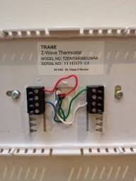
hitachi air conditioning unit instructions I attempted to replace my thermostat with a fancy new Trane z-wave enabled model.
12000 btu split unit air conditioner pricesTo my dismay my home was only wired with a 4 wire setup with no 5 hidden in the bundle. I followed Insx on the web and moved the g (fan wire) on the furnace to the c terminal. Then I put a jumper wire to connect the g and y terminal at the furnace board. I wired the thermostat as shown in the Trane manual while assuming the new C wire in its appropriate position and leaving the fan terminal empty.

The Trane unit is internally jumpered between Rc and Rh. The thermostat powers up fine but as soon as I go to do a heating call, or a cooling call it blows the 3A fuse on the furnace board. I also tried wiring the R wire to Rh on the thermostat but the same result. I have a York TG9S series gas furnace and no other hvac system (no a/c). A Pro1 T725 was used as the previously thermostat even though it's really for a heat pump. I've included pictures of before and after wiring as well as furnace schematics. Click for full size image hvac thermostat home-automation thermostat-c-wire Testor 101 answered, since there is no cooling unit use the cooling wire as C and leave the Y terminal on the thermostat empty. You moved the Green to C on one end but the picture with the transformer in the top left shows Green still on G there it should be on C. The picture below you would pull the green wire off of Green at both the stat and furnace and move it to C/Common, then you jumper Yellow to Green at the furnace.

Comment converted to answer If you don't have cooling, why are you using the Y terminal? If you have only heat, you can use Red for R, Green for G White for W, and Blue forC`. Also, you'll want to check the rating on the transformer (in volt-amperes) in the furnace and the thermostat (in milliamperes). Your pictures have no 24 volt wires going to an AC unit, you show 4 wires at the stat and the 4 wires at the air handler with the G jumped to Y and the Green wires used for Common that looks ok, but nothing from the air handler to any AC unit outdoors as in Yellow and Common. You have a direct short in heat or cool modes yet for cool mode nothing is wired up to an AC unit outside, unlesss there is a splice you are not showing us. Remove the 24 volt wires from the air handler and jump red to green. Does it work or blow a fuse? Jump red to Yellow, if the fuse blows you have a direct short in the board or the 24 vot wiring for the heat mode, since you say either modes blow the sue yet no AC units 24 volt control wiring is wired up I suspect a bad board.
bypass the thermostat and jump red to Greenfor fan, the red to yellow for cool then red to white for heat. If it runs fine your stats bad, if it wont run and blows a fuse the stats not the culprit or its wiring, by jumping red to white at the air handler you remove the thermostat from the equaton. See the Yellow and Blue 24 volt wires going outside to the AC unit? You do not show these anywhere.Browse other questions tagged hvac thermostat home-automation thermostat-c-wire or ask your own question.To wire air conditioning thermostats, you need to know what types of thermostat your air conditioner needs. Heat Pump and regular air conditioner unit has two differences Ac thermostat. So, decide which one. Here are the tools you need to wire thermostat: Make sure there is no 24 voltage running to the air conditioner thermostat. There should be On/Off switch near the furnace. So, turn it Off. If you believe you turn the power Off. Try turning the thermostat Fan to ON position.

If the fan runs, it means there is still 24 volt power to the thermostat. If the indoor blower doesn’t run, it mean the power to the hvac thermostat is off (presume the blower works correctly). This only turns Off the power to the furnace and air conditioning thermostats. It doesn’t turn the air conditioner condenser power Off. You don’t need to worry about that, I just wanted to mention it. I’ll only cover how to wire a thermostat. 24 volt doesn’t hurt (some people), but it will hurts your air conditioner components if you forgot to turn it OFF. Learning how to wire thermostat is simply and not all people see it that way. So, if you decide to wire your own air conditioner thermostat, you do it at your own risk. There are people, who were successful wiring thermostat and there are also who weren’t. For those who weren’t successful wire thermostat waste thermostat, time, money, and could damage air conditioner parts. Air conditioning thermostats wire are color coded in white, yellow, green, red, and (C) common wire.

I had seen common wires are sometime blue, black or brown. Some thermostat wires that coming from the air conditioner unit with four wires and there is no common wire. These four wires are: W for furnace, R for 24 volt, Y for air conditioner unit and G for blower. If the existing Ac thermostat has four wires coming from your furnace and air conditioner unit, Then your new air conditioner thermostat must have four wires to connect to furnace and air conditioner unit. Whenever you unscrew the air conditioning thermostats from the wall, make sure the thermostat wire doesn’t slip back to the drywall. You could twist thermostat wire to pencil to prevent it from slipping to a drywall. The red wire supposed to have 24 volt (hot wire), but we don’t know if the previous owner use the red wire as the hot wire. They could have mix-match the color code, so be careful. Here how you wire a thermostat. Remember, in oldest furnace or air conditioner units. The thermostat wire color tends to fade or it does not using the right color code by previous owner or someone.

That why it’s best to take the wire from existing thermostat and wire it to the new air conditioning thermostats one by one, instead taking all the thermostat wire and try to figure where it goes. In the Ac thermostat subbase, there’re screws or connector. You connect each wire with the Ac thermostat subbase. Air conditioner thermostat color codedLearning how to wire a thermostat or how to wire a heat pump thermostat is simply. The information peoples lack in wire a home thermostat is the thermostat color coded. Here are lists of thermostat wire color coded to help you with wiring hvac thermostat. R – (Red wire) The red wire goes to the thermostat subbase R terminal. This hot wire directly came from the air handler in split central air conditioner units. If it were a package air conditioner units, it came from outside. Red wire supposed to have 24 volt in it. In older AC units color tend to fade and the person, who installed the air conditioning thermostats tend not to uses red as the hot wire (24 V).

For safety reason, always turn off air handler and outdoor units. Y – (Yellow wire) This wire is from air conditioner units (cooling side); it came from the compressor relay and goes to Y terminal in thermostat subbase. Y2 – (generally blue wire) This is the thermostat wire for second stage of cooling. Y wire is for the first compressor (air conditioner units) and Y2 wire is for the second compressors (air conditioner unit). Y2 wires apply only if you have two air conditioner units running from one AC thermostat. W – (White wire) this is the AC thermostat wire from heating unit. The unit could be furnace, oil or gas furnace, boiler or electric furnace. The W wire goes to W terminal on the subbase of air conditioning thermostats. W2 – (Commonly brown wire) This wire is for second stage heating. For example, Heat Pump needs W2 wire for auxiliary heat, so it uses the W2 terminal for auxiliary heat. On some furnaces that has low fire and high fire requires W2 terminal to energize by the AC thermostat.
G – (Green wire) This wire is in air handler blower if it were a split central air conditioner. It came from fan relay and connects it with G terminal on subbase of AC thermostat. If it were package air conditioner units, this wire would come from outdoor. C – (This is 24 volt neutral wire. I had seen this wire color in black, blue, or brown. So you have to read the electrical diagram) This wire is common wire or ground wire. This wire only applies if homeowners have digital thermostats that require electricity to power the thermostat. The black wire is just to complete the 24 volt circuit for the air conditioning thermostats. O – (Orange wire) This wire only applies to Heat Pump. The orange wire is for reversing valve to energize the Heat Pump in cooling mode. B – (Blue wire or different color wire) I had seen in some Heat Pump unit this wire was black. So, you have to read the air conditioner electrical diagram to determine the exact color. This is for the Heat Pump reversing valve to energize the unit in heating mode.

RC – (Red wire) This wire is hot wire (have volt). This RC wire meant to energize the air conditioner unit for cooling. You would see RC terminal has a jumper with RH terminal in the air conditioner thermostat. The reason there was jumper because the air conditioner unit has a single transformer. If it has two transformers you wouldn’t seen a jumper between RC and RH. RH and RC would have it own individual 24 volt from the transformer. RH – (Red wire) This wire is also hot wire. It’s for heating mode wire. Read RC wire for more information on RH wire. E – (Blue, pink, or different color. Check the thermostat manual or air conditioner diagram for color coded). This wire designed for Heat Pump Emergency Heating. The reason Heat Pump have the emergency heating is if any of the major component in air conditioner fails to run. The homeowners would energize the Emergency Heating. That why air conditioning thermostats has less wire comparing to Heat Pump thermostat. Return to air conditioner thermostat from how to wire a thermostat